[Top] [Next]
[Prev]
9.4 Choice of Flip-Flops
After state reduction and state assignment, the next
step in the design process is to choose flip-flop types for the state registers.
The issues are identical to those in the counter case studies of Chapter
7.
Usually, we have to decide whether to use J-K
flip-flops or D flip-flops. J-K devices tend
to reduce the gate count but increase the number of connections. D
flip-flops simplify the implementation process and are well suited for VLSI
implementations, where connections are at more of a premium than gates.
Because the CAD tools mentioned in the previous section were developed to
assist in VLSI implementations, it is not surprising that they implicitly
assume D flip-flops as the targets of the assignment. Their best
assignment may not lead to the minimum logic for a J-K
flip-flop implementation.
The following procedure completes the finite state machine
implementation, given a particular choice of flip-flops:
- Given the state assignments, derive the next-state maps from the state
transition table.
- Remap the next-state maps given the excitation tables for the flip-flops
chosen to implement the state bits.
- Minimize the remapped next-state function.
9.4.1 Flip-Flop Choice for the Four-Bit Sequence Detector
Let's illustrate the procedure with the 4-bit sequence
detector, using the state assignment of Figure 9.39, the encoded state transition
table.

Each state has been replaced by its binary encoding given by the state
assignment.

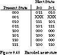
Figure 9.40 is the encoded next-state map, organized according to the
standard binary sequence and showing the don't cares.
D Implementation To obtain the
direct form for determining the state machine implementation with D
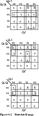
flip-flops, represent the encoded next-state functions as K-maps. Figure
9.41 contains the four-variable K-maps for the next-state functions Q2+,
Q1+, Q0+, given the current
state Q2, Q1, Q0 and the input I. The
reduced equations that describe the inputs to the D flip-flops
are

There are six unique product terms and 15 literals.
In terms of discrete gates, the implementation requires 3 three-input gates,
5 two-input gates, and 4 inverters, a total of 12 gates.

J-K Implementation For the J-K
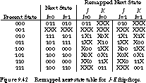
implementation, we begin by remapping the inputs based on the J-K
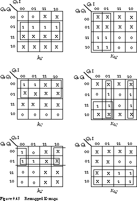
excitation tables. Figure 9.42 gives the remapped next-state table, and
Figure 9.43 shows the K-maps. The J-K logic equations
become


This implementation requires nine unique terms and 14 literals. The gate
count is 1 three-input gate, 6 two-input gates, and 3 inverters, a total
of 10 gates. This is slightly fewer than the D flip-flop implementation.
However, when you use structured logic such as a PLA to implement the functions,
the option with fewer product terms is better. In this case, it would be
the D implementation.
[Top] [Next]
[Prev]
This file last updated on 07/15/96 at 06:40:56.
randy@cs.Berkeley.edu;


